

-
I know that we have some serious amp gurus on this forum so I thought I would ask this question.
I have an original Fender Princeton Reverb from 1979 and a Headstrong Lil' King, which is basically a more powerful Princeton.
Both amps also have the same 12" model speaker and cabinet size; they sound nearly identical.
The spring reverb on the Fender is great and the reverb on the Headstrong seems to have too much low frequency, which muddies up the sound.
I saw online that amp designer Steve Carr was talking about changing the reverb "EQ", has anyone ever tried this or have any info as to how to modify it?
Steve Carr did not go into much detail, he just said that it was possible.
I have tried putting the reverb tank from my Fender into the Headstrong (Both amps have the same model and size reverb tank)
and there was no change, which leads me to believe that some sort of high-pass needs to be added in the reverb send or return on the amp.
Any ideas?
Thanks!
-
08-15-2025 12:33 PM

-
I don't know the schematic of that amp, but if it is a copy of the Princeton, maybe decreasing the bypass capacitors on the reverb send/receive stages
-
Lil king in theory is identical in circuit to a Princeton reverb. My amp tech did this for me on my headstrong. Somehow all the Princeton clones I’ve had don’t quite sound right.
-
Thanks for the responses.
@ omphalopsychos- do you know what the amp tech did exactly?
The amp sounds great just the reverb is not what I prefer.
Were you also not satisfied with the reverb?
Just to be clear, I am not planning to do the modification myself, I just need some info as to what needs to be done.
Thanks.
-
There is a 500 picofarad capacitor in the path leading up to the reverb tank which filters out the low frequencies. As you experienced, reverb doesn't like low frequencies very well. The first thing I would check (after swapping the reverb tanks, which you already did) is to see if Headstrong increased the value of that capacitor for some reason. A larger cap would allow more bass to pass through.
-
No ideas, but a couple of thoughts. High pass filter certainly makes sense, but it might be hard to figure out exactly what values of components to use. And, what sounds good on the test bench may not sound good on a gig.
 Originally Posted by Question
I've had a Boogie where a change in tube type, approved by Mesa, resulted in a very muddy sound. So, maybe ask an expert about a tube change?
Would replacing the tank make a difference? If so, the question becomes, which one would work at all and have a good chance of solving the problem.
No answers here, but those questions come to mind.
-
@Andrew, ok thanks that is exactly the sort of info that I am asking for. So you mean on the send to the reverb tank, correct?
I will not be doing the work myself. I have some basic knowledge but I don't want to mess with high voltage!
An amp tech said he would do the work for me but wasn't sure how to do it; I don't want to pay to have him learn on the job.
Can the capacitors in both amps be measured without removing it from the circuit? I have my Princeton as a model to copy so I could measure the cap there first to see if Headstrong changed its value.
Thanks for the tip!
@rpjazzguitar- I am not aware that changing the reverb tube will affect the reverb's frequency response.
As I wrote in my post, I traded the tank with my Princeton and there was no change.
I can figure out the value of the components by using my Princeton as a model.
Thanks.
-
-
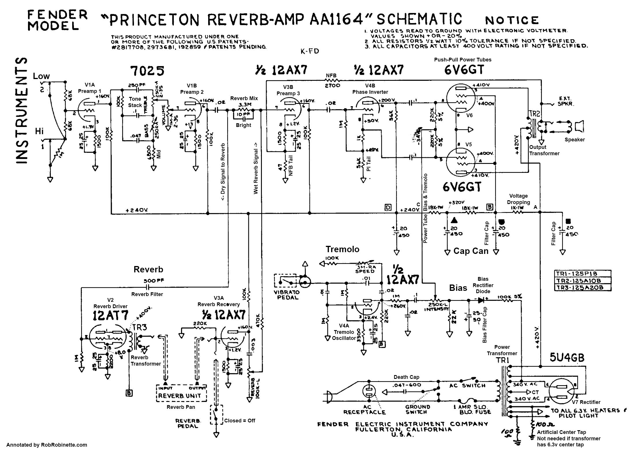
If you look at the schematic I posted, the part to change is the small “Reverb Filter” coupling capacitor feeding the grid of the 12AT7 reverb driver. In the AA1164 Princeton Reverb this cap is 500 pF and it forms a high pass filter with the 1 MOhm grid leak resistor. Stock cutoff works out to about 318 Hz, which means most of the guitar’s low end is already reduced before it gets to the tank.
If the value is larger, more bass gets through and the reverb can sound muddy. The fix is to reduce the value so the cutoff shifts higher and the tank sees less low frequency. Many builders keep it close to stock at 470 pF or 430 pF for a small bass cut. If you want a more obvious tightening, 330 pF or even 250 pF are common choices. Smaller values move the cutoff up into the 480–640 Hz range.
With a 1 MOhm grid leak, here are the approximate cutoffs:
* 500 pF -> 318 Hz (stock)
* 470 pF -> 339 Hz
* 430 pF -> 370 Hz
* 330 pF -> 482 Hz
* 250 pF -> 637 Hz
In the real amp, the exact cutoff can be slightly higher because of the grid-stopper and source impedance, but the relationship is the same. Use a silver mica or polystyrene cap rated at least 500 V. This change only affects the reverb send path so your dry tone stays the same.
Someone tell me if that's wrong bc it was all AI generated for the haters.
-
@omphalopsychos Thanks for the schematic. I think I have one for the Princeton but not for the Headstrong.
If I am reading it correctly with my rudimentary knowledge, the Reverb Filter Capacitor is before the Reverb driver tube, correct?
I asked Andrew; can that capacitor be measured without removing it from the circuit? Or are the PF values printed and readable on the capacitors? Now I just need to find it in the circuit! Anyone have photos of this part of the circuit?
Thanks!
-
Yes, I am referring to the reverb send. It is a small capacitor (one of the smallest) on the eyelet board. Measuring is well and good, but the values should be printed on the outside of the capacitor itself (it may be in code). Originally Posted by Question
-
Thanks very much for the detailed info.
I will have a look next week when I have some time.
-
Here is the location of that capacitor (circled in red):
-
That’s a unique presentation at least to me of circuit layout and component function. Is there a source you could share that would have other Fender amps documented in the same fashion?
Originally Posted by andrew
-
Look here: Originally Posted by srs
Amp Stuff
That website is the source for the layout drawing in the post before.
-
@Andrew Thanks!
-
Good ol' Rob Robinette. What a trove of info on his website! I have referred extensively to his 5E3 pages.
-
Yep. Rob Rob is a great amp resource! Other good ones are Uncle Doug and the Valve Wizard.
-
Hi Andrew and omphalopsychos,
I hope that you guys are still watching this thread.
I finally had some time today to open the amp and start doing the mod.
I easily found the capacitor that you indicated and could read the values.
Values on the cap: BC X5F 501k 1kv
I tried measuring the cap in the circuit and (I think) it says 480k.
I think the soldering job is within my capabilities, as long as I can't accidentally un-solder something that I can't see on the underside of the circuit board.
Using this table that you posted:
* 500 pF -> 318 Hz (stock)
* 470 pF -> 339 Hz
* 430 pF -> 370 Hz
* 330 pF -> 482 Hz
* 250 pF -> 637 Hz
I think I would first like to try the 330pf Capacitor. You wrote "Use a silver mica or polystyrene cap rated at least 500 V."
I don't know much about caps; could you tell me exactly what I need to buy? I don't know what each number on the cap signifies.
I assume that 1kv is 1000kv; as you mentioned use a cap of at least 500V. Is that correct?
Sorry for the layman questions!
I think I will order one cap of each value to see which one works best.
Here are two photos just to make sure that I am replacing the correct cap!
Thanks so much!
-
Is this the correct part?
-
For Fender tube amps with reverb that have the Normal and Vibrato channels, you can take the reverb return cable that goes from the tank to the chassis (the one that goes between the connections labelled "output" at both ends!, see below*), disconnect it at the chassis, put a female RCA to male 1/4 inch adapter plug on the end, and insert that into one of the Normal channel inputs.
Depending on the size of the amp and your preferred cable routing path, you might need the adapter to be female RCA to female 1/4 inch so you can use a patch cord to make the path to the Normal channel input the way you want.
This diverts the reverb return from the Vibrato channel (so the "Reverb" control does not function and there is no reverb in the Vibrato channel) to the Normal channel where the reverb now enjoys an independent volume control and two or three independent tone controls.
You can give the new Normal channel reverb a different EQ from the primary tone of the Vibrato channel you plug your guitar into. Best results will likely be to plug the instrument into the Vibrato input 1 and the reverb return into Normal input 2 (-6 dB) to provide more usable reverb volume knob range for fine tuning.
* This is something that can be reversed back to stock in a few minutes. If you do this, remember that the Fender convention for labeling the reverb connections on the tank and on the chassis is not "signal path in-out" oriented. The labels were for the clarity of assembly - "input" connects to "input", "output" connects to "output". That is, connect the same labels to each other. This is counter intuitive to we who think of signal path, and is a potential problem whenever one is reconnecting a tank. People will troubleshoot for hours thinking input to input and output to output just makes no sense and can't be right! Just know that the labels you connect really do need to be labeled the same and all is well.
-
Yes, you have the right capacitor. It is indeed a 500 picofarad cap ("501" translates to 500 picofarads in capacitor codes). It's good that we confirmed that what you have is indeed the "correct" Fender value and that the builder didn't substitute another value in its place. But it is a little odd that it is sounding so muddy. You can certainly try a smaller cap there. There is a wire connected under the board to that terminal, so exercise some caution when soldering. Fortunately, that immediate section of the board does not contain any high voltages.
-
@Andrew
Thanks.
Just to be clear, the ceramic cap in the photo from the online shop is is the correct replacement, right?
I saw that there were different materials, ceramic etc.
-
Yes, such small cap values are usually ceramic capacitors. However, the material for this purpose is secondary.
As said before, mind the cables below the board connected to both solder points of the cap.
Personally, I don't expect any remarkable change in the reverb sound by changing that 500pF cap to a smaller value. Just my 2c.
-
@bluenote61,
thanks for the reply. Maybe I will have my tech here in town do the soldering just to be safe.
I have done quite a lot of soldering in my studio but not on this type of point to point board.
I am interested as to why you don't think changing this cap will make much of a difference.
Do you think the mod will not change the reverb sound or that it might be due to other factors.
Another user on this thread using the same amp said he did the same mod.
I am trying to make the reverb sound like the nice reverb in my 79' Fender Princeton of which the Headstrong is a copy.
The reverb has a slight ringing resonance at about 400hz, which the Fender does not.
I know from EQ-ing my hardware studio reverbs that this is a frequency that often makes the sound a bit unclear.
I studied music and not electronics so I am very interested in what someone who has more experience with amps has to say.
Thanks!


 Reply With Quote


Interesting Acoustic-Electric 7-String
Today, 06:32 PM in Guitar, Amps & Gizmos